Forging has a long history in China, and it has been continued by the production method of manual workshops. Probably around the beginning of the 20th century. It gradually appeared in the railway, military industry, shipbuilding and other industries with the production method of mechanical industrialization. The main sign of this shift was the use of powerful forging machines.
In the automobile manufacturing process, forging processing methods are widely used. With the advancement of science and technology, the requirements for the accuracy of workpieces have been continuously improved, and the precision forging technology with the advantages of high efficiency, low cost, low energy consumption, and high quality has been more and more widely used. According to the deformation temperature of metal plastic forming, precision cold forging can be divided into cold forging, temperature forming, sub-hot forging, hot precision forging, etc. The auto parts produced include: automobile clutch engagement ring gear, automobile transmission Input shaft parts, bearing rings, automotive constant velocity universal joint sliding sleeve products, automotive differential gears, automotive front axles, etc.

Definition and classification of forging
1. Definition of forging
Forging is a processing method that uses forging machinery to apply pressure to metal blanks to cause plastic deformation to obtain forgings with certain mechanical properties, certain shapes and sizes. It is one of the two major components of forging (forging and stamping).
Forging can eliminate defects such as as-cast porosity produced in the metal smelting process and optimize the microstructure. At the same time, due to the preservation of complete metal flow lines, the mechanical properties of forgings are generally better than castings of the same material. For important parts with high loads and severe working conditions in related machinery, forgings are mostly used, except for plates, profiles or weldments that can be rolled with simpler shapes.
2. Classification of forging
According to different production tools, forging technology can be divided into free forging, module forging, ring rolling and special forging .
Free forging: refers to the processing method of using simple universal tools or directly applying external force to the blank between the upper and lower anvils of the forging equipment to deform the blank to obtain forgings with the required geometric shape and internal quality.
forging: refers to the forging obtained by compressing and deforming a metal blank in a forging die chamber with a certain shape. Die forging can be divided into hot forging, warm forging and cold forging. Warm forging and cold forging are the future development direction of die forging, and also represent the level of forging technology.
Ring rolling: refers to the production of ring parts with different diameters through special equipment ring rolling machines, and is also used to produce wheel-shaped parts such as automobile hubs and train wheels.
Special forging: including roll forging, cross wedge rolling, radial forging, liquid die forging and other forging methods, which are more suitable for the production of parts with special shapes. For example, roll forging can be used as an effective preforming process to greatly reduce the subsequent forming pressure; cross wedge rolling can produce steel balls, transmission shafts and other parts; radial forging can produce large forgings such as barrels and stepped shafts.
According to the forging temperature, forging technology can be divided into hot forging, warm forging and cold forging .
The starting recrystallization temperature of steel is about 727°C, but 800°C is generally used as the dividing line, and those above 800°C are hot forging ; those between 300 and 800°C are called warm forging or semi-hot forging , and forging at room temperature Called cold forging . The forgings used in most industries are hot forging. Warm forging and cold forging are mainly used for forging parts such as automobiles and general machinery. Warm forging and cold forging can effectively save materials.
According to the movement mode of the forging die, forging can be divided into pendulum rolling, pendulum swivel forging, roll forging, cross wedge rolling, ring rolling and cross rolling .
3. Forging materials
The forging materials are mainly carbon steel and alloy steel with various components, followed by aluminum, magnesium, copper, titanium and their alloys, iron-based superalloys, nickel-based superalloys, and deformed alloys of cobalt-based superalloys. Or rolling, but these alloys are relatively difficult to forge due to their relatively narrow plastic zone. The heating temperature, starting forging temperature and final forging temperature of different materials have strict requirements.
The original state of the material is bar stock, ingot, metal powder and liquid metal. The ratio of the cross-sectional area of the metal before deformation to the cross-sectional area after deformation is called the forging ratio.
Correct selection of forging ratio , reasonable heating temperature and holding time , reasonable initial forging temperature and final forging temperature , reasonable deformation amount and deformation speed have a great relationship with improving product quality and reducing cost.
Commonly used forging methods and their advantages and disadvantages
1. Free forging
Free forging refers to the processing method of using simple general-purpose tools or directly applying external force to the blank between the upper and lower anvils of the forging equipment to deform the blank to obtain forgings with the required geometric shape and internal quality. The forging produced by free forging method is called free forging.

Free forging mainly produces forgings with small batches. Forging equipment such as forging hammers and hydraulic presses are used to form blanks to obtain qualified forgings. The basic process of free forging includes upsetting, drawing, punching, cutting, bending, twisting, shifting and forging. Free forging adopts hot forging method.
Free forging process
Including basic process, auxiliary process, finishing process.
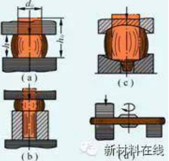
The basic process of free forging: upsetting, drawing, punching, bending, cutting, twisting, shifting and forging, etc., but the three most commonly used processes in actual production are upsetting, drawing and punching.
Auxiliary process: pre-deformation process, such as pressing the jaw, pressing the edge of the steel ingot, cutting the shoulder, etc.
Finishing process: the process of reducing the surface defects of forgings, such as removing the unevenness and shaping of the forging surface.
Advantage:
- Great forging flexibility, can produce small parts less than 100kg, and can also produce heavy parts as large as 300t or more;
- The tools used are simple, general-purpose tools;
- Forging forming is to gradually deform the blank in different regions. Therefore, the tonnage of forging equipment required to forge the same forging is much smaller than that of model forging;
- Low precision requirements for equipment;
- The production cycle is short.
Disadvantages and limitations:
- Production efficiency is much lower than model forging;
- Forgings have simple shapes, low dimensional accuracy, and rough surfaces; workers have high labor intensity and require high technical levels;
- It is not easy to realize mechanization and automation.
2. Die forging
Die forging refers to the forging method in which forgings are obtained by forming blanks with dies on special die forging equipment. The forgings produced by this method are precise in size, small in machining allowance, complex in structure and high in productivity.

Classified according to the equipment used: die forging on hammer, die forging on crank press, die forging on flat forging machine and die forging on friction press, etc.
The most commonly used equipment for hammer die forging is steam-air die forging hammer, anvil-free hammer and high-speed hammer.
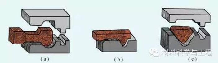
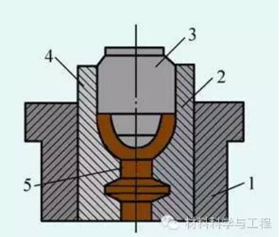
Forging die cavity:
According to their different functions, they can be divided into two categories: die forging die chamber and billet die chamber .
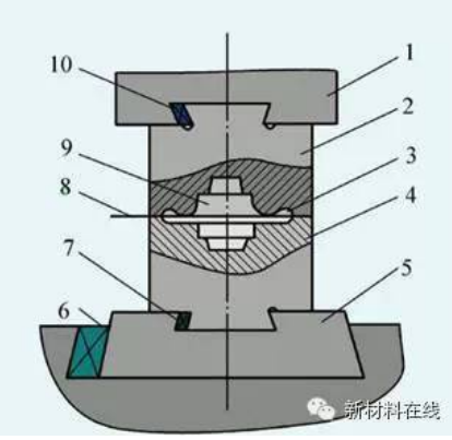
(1—hammer head; 2—upper mold; 3—flash groove; 4—lower mold; 5—die pad; 6, 7, 10—fastening wedge iron; 8—parting surface; 9—die cavity)
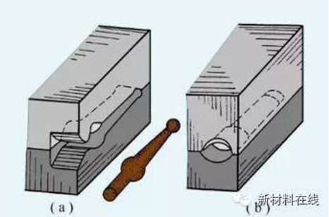
a. Die forging cavity
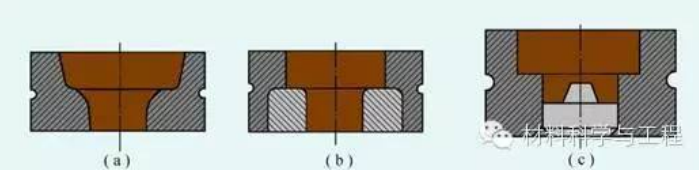
(1) Pre-forging die cavity:
The function of the pre-forging die cavity is to deform the blank to be close to the shape and size of the forging, so that during the final forging, the metal can easily fill the die cavity to obtain the required size of the forging. For forgings with simple shapes or small batches, no pre-forging die chamber is required. The fillet and slope of the pre-forging die cavity are much larger than that of the final forging die cavity, and there is no flash groove.
(2) Final forging die cavity:
The function of the final forging die cavity is to finally deform the blank to the shape and size required by the forging. Therefore, its shape should be the same as that of the forging; but because the forging shrinks when it cools, the size of the final forging die cavity should be larger than that of the forging. Dimensions are enlarged by a shrinkage amount. The shrinkage of steel forgings is taken as 1.5%. In addition, there are flash grooves around the die cavity to increase the resistance of the metal flowing out of the die cavity, to promote the metal to fill the die cavity, and to accommodate excess metal at the same time.
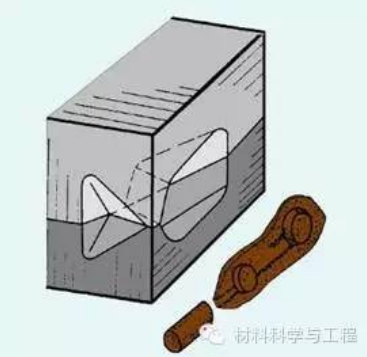
b.Blank mold cavity
For forgings with complex shapes, in order to make the shape of the blank basically conform to the shape of the forging, so that the metal can be distributed reasonably and the cavity can be well filled, it is necessary to make a blank in the blank cavity in advance.
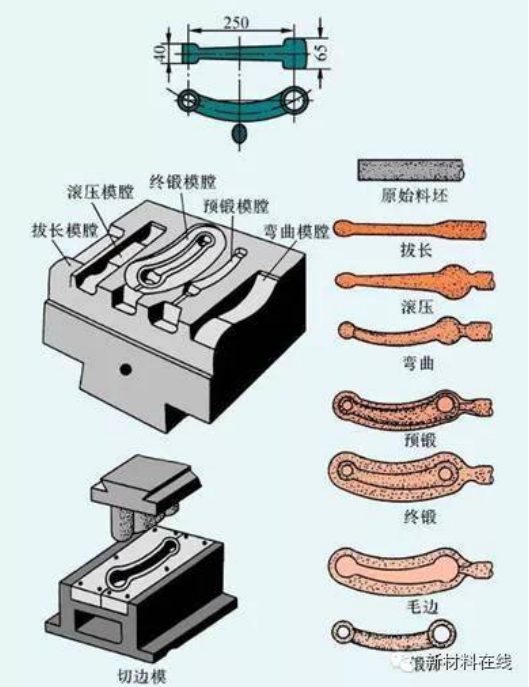
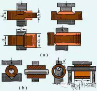
(1) Pull out the die cavity:
It is used to reduce the cross-sectional area of a certain part of the blank to increase the length of the part. There are two kinds of drawing die chambers: open type and closed type.
(2) Rolling die cavity:
It is used to reduce the cross-sectional area of a certain part of the blank to increase the cross-sectional area of another part, so that the metal is distributed according to the shape of the forging. The rolling die cavity is divided into two types: open type and closed type.
(3) Bending cavity:
For curved rod die forgings, a bending die cavity is required to bend the blank.

(4) Cut off the cavity:
It forms a pair of knife edges on the corners of the upper mold and the lower mold to cut metal.
Advantage:
- Higher production efficiency. During die forging, the deformation of the metal is carried out in the die cavity, so the desired shape can be obtained quickly;
- It can forge forgings with complex shapes, and can make the distribution of metal flow lines more reasonable and improve the service life of parts;
- The size of the die forging is more accurate, the surface quality is better, and the machining allowance is smaller;
- Save metal materials and reduce cutting workload.
- Under the condition of sufficient batches, the cost of parts can be reduced.
Disadvantages and limitations:
- The weight of die forgings is limited by the capacity of general die forging equipment, mostly below 7Kg;
- The manufacturing cycle of the forging die is long and the cost is high;
- The investment cost of die forging equipment is larger than that of free forging.
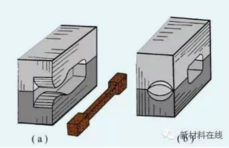
3. Roll forging
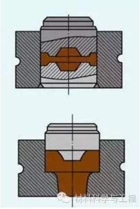
Roll forging refers to a forging process in which a pair of counter-rotating fan-shaped dies are used to plastically deform the billet to obtain the desired forging or forging billet.
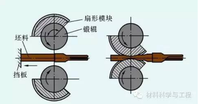
The principle of roll forging deformation is shown above. Roll forging deformation is a complex three-dimensional deformation. Most of the deformed material flows along the length direction to increase the length of the billet, and a small part of the material flows laterally to increase the width of the billet. During the roll forging process, the cross-sectional area of the billet root decreases continuously. Roll forging is suitable for deformation processes such as elongating shafts, rolling slabs and distributing materials along the length direction.
Roll forging can be used to produce connecting rods, twist drills, wrenches, spikes, hoes, picks, and turbine blades. The roll forging process uses the principle of roll forming to gradually deform a blank.
Compared with ordinary die forging, roll forging has the advantages of simple equipment structure, stable production, low vibration and noise, easy automation and high production efficiency.
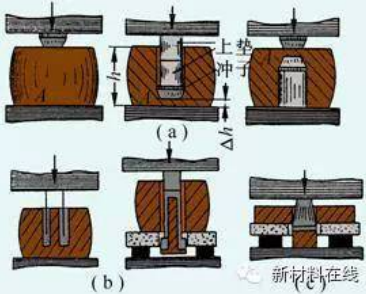
4. Tire die forging
Tire die forging is a forging method that adopts the free forging method to make a billet, and then finally shapes it in the tire mold. It is a forging method between free forging and die forging. There are few die forging equipment, most of which are free forging hammers, which are widely used in small and medium-sized enterprises.
There are many types of tire molds used in tire die forging, and the commonly used ones in production are: type drop, buckle mold, set mold, cushion mold, clamping mold, etc.
The closed cylinder die is mostly used for the forging of rotary forgings. For example, gears with bosses on both ends are sometimes used for forging non-revolving forgings. Closed cylinder die forging is a flash-free forging.
For tire mold forgings with complex shapes, it is necessary to add two half molds (that is, add a parting surface) in the cylinder mold to make a combined cylinder mold, and the blank is formed in the cavity composed of two half molds.
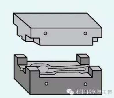
The composite film is usually composed of two parts, the upper and lower molds. In order to match the upper and lower dies and prevent the forgings from shifting, guide posts and guide pins are often used for positioning. Die clamping is mostly used to produce non-revolving forgings with complex shapes, such as connecting rods, fork forgings, etc.
Compared with free forging, tire die forging has the following advantages:
- Since the billet is formed in the die cavity, the forgings are relatively accurate in size, smooth in surface, and the distribution of streamline structure is reasonable, so the quality is high;
- Tire die forging can forge forgings with relatively complex shapes; because the shape of forgings is controlled by the die cavity, the blank is formed faster, and the productivity is 1 to 5 times higher than that of free forging;
- There are few remaining blocks, so the machining allowance is small, which can not only save metal materials, but also reduce machining hours.
Disadvantages and limitations:
- A forging hammer with a larger tonnage is required
- Only small forgings can be produced;
- The service life of the tire mold is low;
- When working, it is generally necessary to move the tire mold manually, so the labor intensity is elatively high;
- Tire die forging is used to produce medium and small batch forgings.
Forging defects and analysis
The raw materials for forging are ingot, rolled material, extruded material and forged billet. Rolled products, extruded materials and forged billets are semi-finished products processed from ingots through rolling, extrusion and forging respectively. In general, the appearance of internal defects or surface defects of ingots is sometimes unavoidable. Coupled with the improper forging process in the forging process, it will eventually lead to defects in the forging. The following is a brief introduction to some common defects in forgings.
1. Forging defects caused by defects in raw materials usually include:
Surface crack
Surface cracks mostly occur on rolled and forged bars, generally in a straight line shape, consistent with the main deformation direction of rolling or forging. There are many reasons for this defect. For example, the subcutaneous air bubbles in the steel ingot elongate along the deformation direction during rolling, and are exposed to the surface and develop deep inside. Another example is that during rolling, if the surface of the billet is scratched, it will cause stress concentration during cooling, which may crack along the scratches and so on. If this kind of crack is not removed before forging, it may expand and cause cracks in the forging during forging.
Fold
The reason for folding is that when the metal billet is in the rolling process, due to the incorrect sizing of the groove on the roll, or the burrs generated by the worn surface of the groove are involved during rolling, forming a certain inclination angle with the surface of the material crease. For steel, there are iron oxide inclusions in the creases and decarburization around them. If the fold is not removed before forging, it may cause the forging to fold or crack.
Scarring
Scalping is a peelable film on a localized area on the surface of the rolled material.
The formation of scars is due to the splashing of molten steel during casting and condensation on the surface of the ingot, and it is pressed into a thin film during rolling, which is attached to the surface of the rolled material, which is scarring. After forging, the forging is pickled and cleaned, and the film will peel off and become a surface defect of the forging.
Layered fracture
The characteristic of layered fracture is that its fracture or section is very similar to broken slate and bark.
Layered fractures mostly occur in alloy steels (chromium-nickel steel, chromium-nickel-tungsten steel, etc.), and are also found in carbon steels. The occurrence of this defect is due to defects such as non-metallic inclusions, dendrite segregation and porosity in the steel, which are elongated along the rolling direction during the forging and rolling process, making the steel sheet-like. If there are too many impurities, there is a danger of delamination and cracking in forging. The more serious the lamellar fracture, the worse the plasticity and toughness of the steel, especially the low transverse mechanical properties, so the steel with obvious lamellar defects is unqualified
Bright lines (bright areas)
The bright lines are thin reflective lines that appear crystalline and shiny on the longitudinal fracture, most of which run through the entire fracture, and most of them are generated in the axial center.
Bright lines are mainly caused by alloy segregation. Slight bright lines have little effect on the mechanical properties, and severe bright lines will significantly reduce the plasticity and toughness of the material.
Non-metallic inclusions
Non-metallic inclusions are mainly formed during the cooling process of smelting or casting molten steel due to chemical reactions between components or between metals, furnace gas, and containers. In addition, during metal smelting and casting, since refractory materials fall into molten steel, inclusions can also be formed, which are collectively referred to as slag inclusions. On the cross-section of the forging, non-metallic inclusions can be distributed in the form of points, flakes, chains or clusters. Severe inclusions are likely to cause cracking of forgings or reduce the performance of materials.
Carbide segregation
Carbide segregation often occurs in alloy steels with high carbon content. It is characterized by the accumulation of more carbides in local areas. It is mainly caused by the ledeburite eutectic carbide and secondary network carbide in the steel, which are not broken and evenly distributed during blanking and rolling. Carbide segregation will reduce the forging deformation performance of steel and easily cause cracking of forgings. Forgings are prone to local overheating, overburning and quenching cracking during heat treatment and quenching.
Aluminum oxide film
The aluminum alloy oxide film is generally located on the web of the die forging and near the parting surface. On the low-magnification tissue, it is a fine crack, and on the high-magnification tissue, it is vortex-shaped. The characteristics of the fracture can be divided into two categories: one, it is flat and flake, and the color ranges from silver gray, light yellow to brown, dark brown ; Second, in the form of small, dense and flashing dots.
The aluminum alloy oxide film is formed when the exposed melt surface interacts with water vapor or other metal oxides in the atmosphere during the casting process and is drawn into the interior of the liquid metal during the transfer process.
The oxide film in forgings and die forgings has no obvious effect on the longitudinal mechanical properties, but has a greater impact on the mechanical properties in the height direction, which reduces the strength properties in the height direction, especially the elongation in the height direction, impact toughness and resistance in the height direction. corrosion performance
White dot
The main feature of the white spot is a round or oval silver-white spot on the longitudinal fracture of the billet, and a fine crack on the transverse fracture. The white spots vary in size, and the length ranges from 1 to 20 mm or longer. White spots are common in nickel-chromium steel, nickel-chromium-molybdenum steel and other alloy steels, and are also found in ordinary carbon steel, which are hidden internal defects. White spots are produced under the joint action of hydrogen, structural stress and thermal stress during phase transformation, and are more likely to occur when the hydrogen content in the steel is high and the cooling (or heat treatment after forging) is too fast after hot press processing.
Forgings forged from steel with white spots are prone to cracks during heat treatment (quenching), and sometimes even fall off in pieces. White spots reduce the plasticity of steel and the strength of parts, and are stress concentration points. Like sharp cutters, under the action of alternating loads, it is easy to become fatigue cracks and cause fatigue damage. Therefore, white spots are absolutely not allowed in forging raw materials.
Coarse crystal ring
Coarse grain rings are often defects in extruded rods of aluminum alloys or magnesium alloys.
Extruded rods of aluminum and magnesium alloys supplied after heat treatment often have coarse grained rings in the outer layer of their circular sections. The thickness of the coarse crystal ring increases gradually from the beginning to the end of extrusion. If the lubrication conditions during extrusion are good, the coarse crystal rings can be reduced or avoided after heat treatment. Conversely, the thickness of the ring will increase.
The reason for the coarse crystal ring is related to many factors. But the main factor is due to the friction generated between the metal and the extrusion barrel during the extrusion process. This friction causes the grains in the outer layers of the cross-section of the extruded rod to be much more fragmented than the grains in the center of the rod. However, due to the influence of the cylinder wall, the temperature in this area is low, and the recrystallization is not complete during extrusion. When quenching and heating, the unrecrystallized grains recrystallize and grow up to swallow the recrystallized grains, so coarse grains are formed on the surface. ring.
The blank with coarse grain ring is easy to crack during forging, if the coarse grain ring remains on the surface of the forging, the performance of the part will be reduced.
Shrink tube residue
The shrinkage tube residue is generally caused by the concentrated shrinkage cavity generated in the riser part of the steel ingot, which is left inside the steel during blanking and rolling.
Dense inclusions, looseness or segregation generally appear in the area near the shrinkage tube residue. Irregular wrinkled gaps in lateral low magnification. It is easy to cause cracking of forgings during forging or heat treatment.
2. Defects caused by improper material preparation and their impact on forgings
The defects caused by improper material preparation are as follows.
Cut oblique
Slanting is the inclination of the end surface of the blank relative to the longitudinal axis exceeding the specified allowable value due to the lack of compaction of the bar when loading and unloading on the sawing machine or punching machine. Severe beveling, folds may form during forging.
Billet ends are bent and burred
When loading and unloading on a shearing machine or punching machine, due to the excessive gap between the cutting blades or cutting die edges or the unsharp cutting edge, the blank is bent before being cut, and as a result, part of the metal is squeezed into the blade or die. In the gap, a drooping burr is formed at the end.
Blanks with burrs are prone to local overheating and overburning when heated, and are prone to folding and cracking during forging.
Blank end face depression
When loading and unloading on the shearing machine, because the gap between the scissor blades is too small, the upper and lower cracks on the metal section do not overlap, resulting in secondary shearing. As a result, part of the end metal is pulled off, and the end surface becomes concave. Such blanks are prone to folding and cracking during forging.
End crack
When shearing large-section alloy steel and high-carbon steel bars in a cold state, cracks are often found at the ends 3 to 4 hours after shearing. The main reason is that the unit pressure of the blade is too large, so that the circular cross-section blank is flattened into an oval shape, and a large internal stress is generated in the material at this time. The flattened end face strives to restore its original shape, but under the action of internal stress, cracks often appear within a few hours after cutting. When the material hardness is too high, the hardness is uneven, and the material segregation is serious, shear cracks are also prone to occur.
For blanks with end cracks, the cracks will further expand during forging.
Gas cutting crack
Gas cutting cracks are generally located at the end of the billet, which is caused by the tissue stress and thermal stress generated during gas cutting because the raw material is not preheated before gas cutting.
For blanks with gas cutting cracks, the cracks will further expand during forging. Therefore, it should be pre-cleared before forging.
Convex core cracking
When the lathe is blanked, a convex core is often left in the center of the end face of the bar. During the forging process, since the section of the convex core is small and the cooling is fast, its plasticity is low, but the section of the blank matrix is large, the cooling is slow, and the plasticity is high. Therefore, the sudden junction of the cross-section becomes the place where the stress is concentrated, and the plasticity difference between the two parts is relatively large, so under the action of the hammer force, cracks are easily caused around the convex core.
3. Defects often caused by improper heating process
Defects caused by improper heating can be divided into:
- Defects caused by changes in the chemical state of the outer layer of the billet due to the influence of the medium, such as oxidation, decarburization, carburization, sulfurization, copperization, etc.;
- Defects caused by abnormal changes in the internal structure, such as overheating, overheating and underheating;
- Blank cracking due to excessive internal stress (such as temperature stress, tissue stress) due to uneven temperature distribution inside the billet.
Some of the common pitfalls are described below.
Decarbonization
Decarburization refers to the phenomenon that the carbon on the surface of the metal is oxidized at high temperature, so that the carbon content of the surface is significantly lower than that in the interior.
The depth of the decarburization layer is related to the composition of the steel, the composition of the furnace gas, the temperature and the holding time at this temperature. Heating in an oxidizing atmosphere is prone to decarburization, high-carbon steel is easy to decarburize, and steel with a large silicon content is also easy to decarburize.
Decarburization reduces the strength and fatigue performance of the parts, and weakens the wear resistance.
Carbon increase
Forgings heated by oil furnaces often have carburization on the surface or part of the surface. Sometimes the thickness of the carburized layer reaches 1.5-1.6mm, the carbon content of the carburized layer reaches about 1% (mass fraction), and the carbon content of local points even exceeds 2% (mass fraction), and ledeburite structure appears.
This is mainly due to the heating of the oil furnace. When the billet is located close to the nozzle of the oil furnace or in the area where the two nozzles cross the fuel injection area, the combustion is not complete because the oil and air are not mixed well. A reducing carburizing atmosphere is formed on the surface of the blank, thereby producing the effect of surface carburization.
Carburization makes the machining performance of forgings worse, and it is easy to hit the knife when cutting.
Overheat
Overheating refers to the phenomenon that the heating temperature of the metal blank is too high, or the residence time in the specified forging and heat treatment temperature range is too long, or the grain size is coarse due to the excessive temperature rise due to the thermal effect.
Carbon steel (hypoeutectoid or hypereutectoid steel) tends to appear Widmanstatten structure after overheating. After the martensitic steel is overheated, the intragranular texture often appears, and the tool and die steel is often characterized by the angulation of primary carbides to determine the overheated structure. After the titanium alloy is overheated, obvious β-phase grain boundaries and straight and elongated Widmanstatten structures appear. After the alloy steel is overheated, the fracture will appear stone fracture or strip fracture. The overheated structure, due to the coarse grain, will cause the reduction of mechanical properties, especially the impact toughness.
Generally, after normal heat treatment (normalizing, quenching) of overheated structural steel, the structure can be improved and the performance will be restored. This overheating is often called unstable overheating; (including high temperature normalizing), annealing or quenching, the overheating structure cannot be completely eliminated, and this overheating is often called stable overheating.
Burnt
Overburning means that the heating temperature of the metal billet is too high or the residence time in the high-temperature heating zone is too long. Oxygen and other oxidizing gases in the furnace penetrate into the gaps between metal grains and oxidize with iron, sulfur, carbon, etc. to form The eutectic of the fusible oxide is destroyed, the connection between the grains is destroyed, and the plasticity of the material is sharply reduced. Severely overburned metal will crack with a light blow when it is pulled out, and transverse cracks will appear at the overburned part when it is pulled out.
There is no strict temperature boundary between overheating and overheating. Generally, overburning is judged by the oxidation and melting of grains. For carbon steel, the grain boundaries melt during overburning, and when severely oxidized tool and die steels (high-speed steel, Cr12 steel, etc.) are overfired, fishbone-like ledeburite appears at the grain boundaries due to melting. When the aluminum alloy is over-burned, there are grain boundary melting triangles and remelting balls. After the forging is burnt, it is often impossible to save it and has to be scrapped.
Heating crack
When heating large steel ingots with large cross-sectional dimensions and high-alloy steel and high-temperature alloy billets with poor thermal conductivity, if the heating rate is too fast at the low temperature stage, the billets will generate great thermal stress due to the large temperature difference between inside and outside. In addition, the blank has poor plasticity due to the low temperature at this time. If the value of thermal stress exceeds the strength limit of the blank, heating cracks radiating from the center to the surroundings will occur, causing the entire section to crack.
Copper brittle
Copper brittleness is cracked on the surface of the forging. When observed at high magnification, light yellow copper (or copper solid solution) is distributed along the grain boundaries.
When the billet is heated, if copper oxide scraps remain in the furnace, the oxidized steel is reduced to free copper at high temperature, and the molten steel atoms expand along the austenite grain boundary, weakening the connection between the grains. In addition, when the copper content in steel is high [>2% (mass fraction)], if heated in an oxidizing atmosphere, a copper-rich layer is formed under the oxide scale, which also causes steel embrittlement.
4. Defects often caused by improper forging process
Defects caused by improper forging process usually have the following types
Large grain
Large grains are usually caused by too high initial forging temperature and insufficient deformation, or too high final forging temperature, or the degree of deformation falls into the critical deformation zone. If the aluminum alloy is deformed too much, it will form a texture; if the deformation temperature of the superalloy is too low, it may also cause coarse grains when the mixed deformation structure is formed.
Coarse grains will reduce the plasticity and toughness of forgings, and the fatigue performance will decrease significantly.
Uneven grain
Uneven grains mean that the grains in some parts of the forging are particularly coarse, while some parts are smaller. The main reason for the uneven grains is that the uneven deformation of the billet makes the grains broken to different degrees, or the deformation degree of the local area falls into the critical deformation area, or the local work hardening of the superalloy, or the local grain size during quenching and heating. thick. Heat-resistant steels and high-temperature alloys are particularly sensitive to grain inhomogeneity. Uneven grains will significantly reduce the durability and fatigue performance of forgings.
Chill phenomenon
During forging deformation, due to the low temperature or too fast deformation speed, and too fast cooling after forging, the softening caused by recrystallization may not keep up with the strengthening (hardening) caused by deformation, so that the inside of the forging after hot forging still partially retains cold deformed tissue. The existence of this organization increases the strength and hardness of the forging, but reduces the plasticity and toughness. Severe chilling and hardening may cause forging cracks.
Crack
Forging cracks are usually caused by large tensile stress, shear stress or additional tensile stress during forging. The part where the crack occurs is usually the part with the highest stress and the thinnest thickness of the billet. If there are microcracks on the surface and inside of the blank, or there are structural defects in the blank, or the plasticity of the material is reduced due to improper thermal processing temperature, or the deformation speed is too fast, the degree of deformation is too large, and the plasticity index allowed by the material is exceeded, etc. Cracks may occur in processes such as drawing, punching, reaming, bending and extrusion.
Crack
Forging cracks are shallow tortoise-like cracks on the surface of forgings. Surfaces subjected to tensile stress during forging forming (for example, underfilled protrusions or portions subject to bending) are most prone to this defect.
The internal causes of cracking may be various:
- The material contains too many fusible elements such as Cu and Sn;
- When heated at high temperature for a long time, there is copper precipitation on the surface of the steel material, coarse grains on the surface, decarburization, or the surface that has been heated many times;
- The sulfur content of the fuel is too high, and sulfur seeps into the surface of the steel material.
Flash crack
Forging flash cracks are cracks generated at the parting surface during die forging and trimming. The reasons for flash cracks may be: ①During the die forging operation, the metal flows strongly due to the heavy blow, resulting in the phenomenon of rib penetration. ②The trimming temperature of magnesium alloy die forgings is too low; the trimming temperature of copper alloy die forgings is too high.
Parting surface crack
Forging parting surface cracks refer to cracks generated along the forging parting surface. There are many non-metallic inclusions in the raw materials, and the flow and concentration of the parting surface during die forging or the shrinkage tube residue often form parting surface cracks after being squeezed into the flash during die forging.
Fold
Forging folds are formed when oxidized surface metal joins together during metal deformation. It can be formed by the convection of two (or more) metals; it can also be formed by the rapid and large flow of a metal that brings the surface metal of the adjacent part to flow, and the two merge; it can also be due to deformation. The metal is bent and reflowed; it can also be formed by local deformation of part of the metal and being pressed into another part of the metal. Folding is related to the shape of raw materials and blanks, the design of the mold, the arrangement of the forming process, the lubrication situation and the actual operation of forging.
Forging and folding not only reduce the load-bearing area of parts, but also often become a source of fatigue due to the stress concentration here during work.
Flow through
Forging through flow is a form of improper distribution of streamlines. In the through-flow zone, the streamlines originally distributed at a certain angle merge together to form a through-flow, which may cause a large difference in the size of the grains inside and outside the through-flow zone. The reason for the flow-through is similar to that of the fold. It is formed by two strands of metal or one metal leading to another metal, but the metal in the flow-through part is still a whole.
Forging through-flow reduces the mechanical properties of forgings, especially when the difference between the grains on both sides of the through-flow zone is large, the performance reduction is more obvious.
Unsmooth distribution of streamlines in forgings
The unsmooth distribution of streamlines in forgings refers to the occurrence of streamline disturbances such as streamline cuts, backflows, and eddy currents at the low magnification of forgings. If the mold design is improper or the forging method is unreasonable, the streamline of the prefabricated blank will be disordered; the improper operation of the workers and the wear of the mold will cause the metal to flow unevenly, which can make the streamline distribution of the forgings not smooth. Unsmooth streamlines will reduce various mechanical properties, so for important forgings, there are requirements for streamline distribution.
Cast tissue residue
Forging and casting structure residues mainly appear in forgings that use ingots as blanks. The as-cast structure mainly remains in the difficult deformation zone of the forging. Insufficient forging ratio and improper forging method are the main reasons for the residual casting structure.
The residual forging and casting structure will reduce the performance of the forging, especially the impact toughness and fatigue performance.
Carbide segregation level does not meet the requirements
The level of forged carbide segregation does not meet the requirements mainly in ledeburite tool and die steel. The main reason is that the carbides in the forgings are unevenly distributed, concentrated in large blocks or distributed in a network. The main reason for this defect is that the carbide segregation level of the raw material is poor, and forgings with insufficient forging ratio or improper forging method are prone to local overheating and quenching cracking during heat treatment and quenching. The resulting cutting tools and molds are easy to chip when used.
Banded tissue
Forged banded structure is a structure in which ferrite and pearlite, ferrite and austenite, ferrite and bainite, ferrite and martensite are distributed in bands in forgings, and they often appear In hypoeutectic steels, austenitic steels and semi-martensitic steels. This kind of structure is a banded structure produced during forging deformation under the coexistence of two phases, which can reduce the transverse plasticity index of the material, especially the impact toughness. It is often easy to crack along the ferrite band or the junction of the two phases during forging or part work.
Partial underfill
Insufficient forging local filling mainly occurs in ribs, convex corners, corners, and rounded corners, and the size does not meet the requirements of the drawing. The reasons may be: ① low forging temperature, poor metal fluidity; ② insufficient tonnage of equipment or insufficient hammering force; ③ unreasonable design of billet mold, unqualified billet volume or cross-sectional size; ④ accumulation of scale or welding in the die cavity Alloy deformed metal.
Undervoltage
Forging underpressure refers to the general increase of the size perpendicular to the direction of the parting surface. The reasons may be: ①The forging temperature is low. ②Insufficient equipment tonnage, insufficient hammering force or insufficient hammering times.
Shift
Forging misalignment is the displacement of the forging along the upper half of the parting surface relative to the lower half. The reasons may be: ①The gap between the slider (hammer head) and the guide rail is too large; ②The design of the forging die is unreasonable, and there is no lock or guide post to eliminate the misalignment force; ③Poor installation of the mold.
Axis bending
The axis of the forged forging is bent, and there is an error in the geometric position of the plane. The reasons may be: ① not paying attention when the forging is out of the mold; ② uneven force when cutting the edge; ③ different cooling speeds of each part when the forging is cooling; ④ improper cleaning and heat treatment.
5. Defects often caused by improper cooling process after forging
Defects caused by improper cooling after forging usually have the following types.
Cooling crack
During the cooling process after forging, the inside of the forging will generate large thermal stress due to excessive cooling rate, and may also cause large structural stress due to structural transformation. If these stresses exceed the strength limit of the forging, smooth and slender cooling cracks will occur in the forging.
Network carbide
Forging When forging steel with high carbon content, if the stop forging temperature is high and the cooling rate is too slow, carbides will be precipitated in a network along the grain boundaries. For example, when bearing steel is cooled slowly at 870-770°C, carbides will precipitate along the grain boundaries.
Forged network carbides are easy to cause quenching cracks during heat treatment. In addition, it also deteriorates the performance of the parts.
6. Defects often caused by improper post-forging heat treatment process
Defects caused by improper post-forging heat treatment process usually include:
Hardness is too high or hardness is not enough
The reasons for the insufficient hardness of forgings caused by improper post-forging heat treatment process in forging are: ①The quenching temperature is too low; ②The quenching heating time is too short; ③The tempering temperature is too high; The chemical composition is unqualified, etc.
The reasons for the high hardness of forgings caused by improper post-forging heat treatment process in forging are: ① cooling too fast after normalizing; ② too short heating time for normalizing or tempering; ③ unqualified chemical composition of steel, etc.
Uneven hardness
The main cause of uneven hardness caused by forging is improper heat treatment process regulations, such as too much furnace charge at one time or too short holding time; or local decarburization of forgings caused by heating.
7. Defects often caused by improper cleaning process of forgings
The defects that occur during the cleaning of forging forgings usually include the following types.
Over pickling
Excessive forging pickling will make the surface of forgings loose and porous. This kind of defect is mainly caused by the acid depth being too high and the forging staying in the pickling tank for too long, or because the surface of the forging is not cleaned, and the acid liquid remains on the surface of the forging.
Corrosion crack
Forged martensitic stainless steel forgings If there is a large residual stress after forging, it is easy to produce fine mesh corrosion cracks on the surface of the forgings during pickling. If the structure is thicker, the formation of cracks will be accelerated.
Application of precision forging in automobile industry
In recent years, due to the rapid development of precision forging technology, the progress of the automobile manufacturing industry has been promoted. Cold forgings and warm forgings are increasingly used in the automotive industry, and the shape of the product is getting closer to the final shape. Precision forging will develop accordingly with the progress of future processes and related technologies. In addition, based on the purpose of reducing production costs, reducing product weight, simplifying part design and manufacturing, and enhancing product added value, the field of metal plastic forming is actively developing towards high-precision net-shape forming technology.
Net shape is defined as follows:
- Compared with traditional plastic forming (Plastic Forming), it can obtain smaller follow-up mechanical processing, which can meet the size and tolerance requirements of the parts.
- The forming process that meets the size and tolerance requirements of the part without subsequent machining at important parts of the formed part.
- Within the size and tolerance range of the parts, forgings may not require the forming process of subsequent machining.
Metal plastic processing is now developing towards three major goals:
- Product precision (net-shape parts development)
- Rationalization of process (the principle of process integration and application is based on the minimum investment cost and production cost)
- Automation and labor saving
